
By using only high quality materials that we constantly further develop with our various partners, we provide the basis for a long operating life of our heating elements.
As the thermal load furthermore, however, depends on the exact operating conditions of the heating element such as
as well as on the dimensioning and configuration such as
the life of GC-heat heating elements is variable.
Our engineering team will be pleased to assist you with an individual design for your specific application.
The nominal diameter of our ground cartridge heaters "GC-cart" is delivered with an upper deviation of -0,02 mm and a lower deviation of -0,06 mm.
In order to keep the airgap between cartridge sheath and bore hole as small as possible, we recommend construction according to tolerance H7.
Please note that there are specific requirements regarding the drill depth when using "GC-cart EX".
The electrical power (P) is calculated by multiplying the voltage (U) by the current (I).
Electrical heating elements are ohmic resistors. According to Ohm's law therefore follows:
P = U²/R
with U for the voltage [V], R for the resistance in [Ohm] and P for the power in [W].
Lower than nominal voltage results in a lower power output. The target temperature may not be reached.
Doubling the voltage with unvarying resistance results in quadrupled power.
Increasing the nominal voltage might cause intolerant high heating power which can destroy the heating element.
The specific electrical resistance of the heating wire is reduced due to the cold forming during the production process. The resistance increases upon heating up the element for the first time.
The aforementioned process is dependent on a variety of factors and is taken into account by us with the dimensioning of 5 - 9 %.
The rated power is designed for the cold condition of the heating element after the first heating process.
Thus, the resistance of the GC-heat cartridge heater upon delivery and in cold condition is approx. 7 % lower and the first switch-on power is approx. 7 % higher than the rated power.
The specific electrical resistance depends on the temperature.
In terms of the heating wire this means that the resistance increases by approx. 4,5 % from 20 °C up to 1200 °C (referring to the 20 °-indication).
As a result, the operating power is approx. 2 - 4 % lower than the switch-on power (subject to the temperature of the heating wire).
Heating elements must be stored dry and dust free.
As not all heating elements have connection heads with humidity protection, the filling might absorb ambient humidity which results in a decrease of the insulation resistance.
During storage and "out of operation" times it is therefore important to ensure a dry and dust free athmosphere.
For commissioning of the heating elements we furthermore recommend a "starting circuit process".
The fillings of heating elements absorb ambient humidity which leads to a decrease of the insulation resistance.
"Starting circuit processes" heat the element for a specific time period with reduced power to a certain temperature (e.g. 120 °C) before heating the element up to the specified temperature with full power.
The aforementioned process ensures that absorbed humidity can evaporate and leakage currents are reduced.
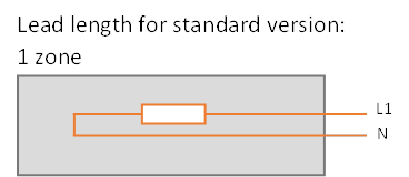
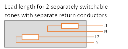
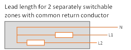
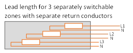
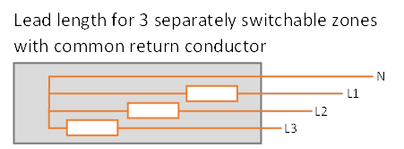
With the help of a power distribution, the cartridge can be heated to different degrees. Separately switchable zones also offer the advantage of being able to switch individual areas on and off.
Depending on the diameter and type of wiring, a maximum of six separately switchable zones can be realized.

For identification and differentiation purposes, the individual zones and associated leads are provided with different lead lengths and, where possible, with different lead colors.
 | |||||||||||
 | |||||||||||
 | |||||||||||
 | |||||||||||
 | |||||||||||
 | |||||||||||
If you have any further questions, our experts will be happy to advise you. Customer-specific requests that deviate from this are possible and can be manufactured based on your application situation if required.
Connection extensions have to be made by a qualified person using suitable crimp barrels, wire-end sleeves, connection elements and insulation materials and in accordance with the general rules of engineering as far as the cross-sections are concerned.
The electrical and mechanical characteristics of compensating conductors for thermoelements are specified in DIN EN 60584-3 and DIN 43 713 and DIN 43 722.
They are either made from the same material as the element itself (thermo-lead, extension cable) or from special materials with the same thermo-electrical characteristics in restricted temperature ranges.
It should be noted that with increasing lead-lengths larger measurement errors may occur and a signal conversion might become necessary.
Please feel free to contact us. Our experts will be glad to advise you and we will do our utmost to execute your order according to your specific needs.
Leads:
G = glass silk insulated leads, max. 350 °C
SFG = glass silk insulated leads, strengthened version max. 450 °C
M = high-temperature glass silk insulated leads, max. 600 °C
T = PTFE leads, max. 260 °C
SLV = silicone leads, max. 180 °C
SLF = highly flexible silicone leads, max. 180 °C
SIK = silicone cable, max. 180 °C
Beaded leads:
P = ceramic beads, max. 750 °C
Note:
The temperatures mentiond above refer to static laying only.
Especially glass silk insulated leads are not suitable for moving applications as the silicone impregnation escapes upon temperatures of more than 200 °C and the sheathing loses its flexibility.
Pay attention to the minimum permissible bending radii when installing the leads.
Static laying: R > 5xAD
Moving application and glass silk insulated leads: R > 7,5 to 10 xAD
(AD = outer diameter of leads)
Usually spiraled coils are manufactured with a minor undersize of the inner diameter which results in a clamping effect.
≤ 12 mm inner diameter of -0.05 / -0.2 mm
> 12 mm inner diameter of -0.1 / -0.3 mm
To mount the "spiral" it has to be twisted at the ends in opposite directions in order to slightly widen it. Then slide the heating element onto the nozzle and release the twisting and tension.
Twist only slightly! There must not ouccur a permanent deformation of the heating element!